Flux Core Welding Settings Chart
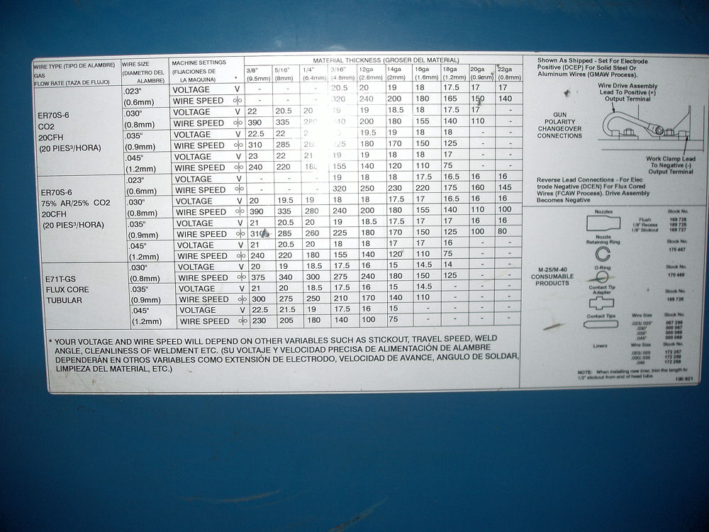
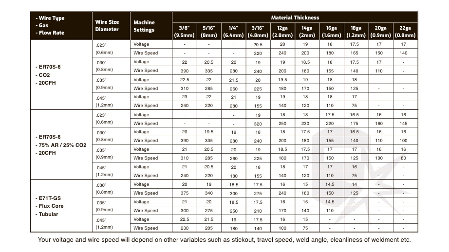
Flux Core Welding Settings Chart - Web flux core welding settings chart. Techniques for optimal 1/16 flux core welding. There are many mig setting charts available from manufacturers that all vary. Web what material are you welding? Web utilizing a welding amperage chart specifically tailored for flux core welding is indispensable. This chart is essential for achieving proper weld. For instance, if you want to want to work with a wire diameter of 0.30mm and 9.5mm material thickness, leave the welder o 19 and 340. Web download the app version of the weld setting calculator for easy reference! These parameters determine the heat input and the amount of welding wire deposited into the weld. The filler wire also acts as the electrode to start the arc and feeds into the weld puddle to. Web flux core welding settings chart. There are many mig setting charts available from manufacturers that all vary. Web utilizing a welding amperage chart specifically tailored for flux core welding is indispensable. The wire is continuously fed into the weld area, and as the filler metal melts, it. In gas metal arc welding (gmaw), you won’t be using a stick electrode or a filler rod. Properly adjusting these parameters is crucial for achieving an optimal balance between penetration and deposition rate. Web how much voltage and amperage a weld requires depends on metal thickness, joint configuration, welding position and wire diameter. Parameters for 1/16 flux core wire. Web the flux core welding settings chart provides detailed information about the recommended settings for flux core welding, including wire speed, voltage, and polarity. Techniques for optimal 1/16 flux core welding. Web comprehending flux core mig welding entails employing the correct wire speed and voltage settings for optimal outcomes. Web utilizing a welding amperage chart specifically tailored for flux core welding is indispensable. For instance, if you want to want to work with a wire diameter of 0.30mm and 9.5mm material thickness, leave the welder o 19 and 340. These parameters. Instead, everything you need to deposit a weld comes from a spool of metal wire. Also, consider the amperage settings and the task at hand. Reference charts are available on your power source to help set the correct voltage and wire feed speed based on the wire diameter and material thickness. Longevity is recognized worldwide for providing reliable welding, cutting,. Techniques for optimal 1/16 flux core welding. 1/16 flux core wire settings. For different welding positions and welding types the wire parameters happen to be different every time. Basics of 1/16 flux core wire. The filler wire also acts as the electrode to start the arc and feeds into the weld puddle to. When you’re looking for the right settings for your lincoln 140 mig welder. These parameters determine the heat input and the amount of welding wire deposited into the weld. However, you will need special wire if you plan to weld other metals, such as aluminum. Techniques for optimal 1/16 flux core welding. There are many mig setting charts available from. Reference charts are available on your power source to help set the correct voltage and wire feed speed based on the wire diameter and material thickness. The wire is continuously fed into the weld area, and as the filler metal melts, it. There is some nuance to it. It’s worth knowing that lincoln electric sells the 140 mig welder under. The wire is continuously fed into the weld area, and as the filler metal melts, it. Web flux core welding settings chart. Longevity is recognized worldwide for providing reliable welding, cutting, and power generating equipment. The lincoln weld pak 140 hd k2514 mig welder is the same as the: Make sure your polarity is correct. There is some nuance to it. Joint design, fitup, backup, position, bead size and stickout may alter conditions. Web download the app version of the weld setting calculator for easy reference! When you’re looking for the right settings for your lincoln 140 mig welder. Web our 7 tips & tricks for beginner flux core welding 1. Web here goes a chart for 0.045 flux core vertical settings depending on several welding positions. For instance, if you want to want to work with a wire diameter of 0.30mm and 9.5mm material thickness, leave the welder o 19 and 340. Web what material are you welding? But before using these values, we suggest that you have a decent. Web utilizing a welding amperage chart specifically tailored for flux core welding is indispensable. The lincoln weld pak 140 hd k2514 mig welder is the same as the: The filler wire also acts as the electrode to start the arc and feeds into the weld puddle to. In gas metal arc welding (gmaw), you won’t be using a stick electrode. Properly adjusting these parameters is crucial for achieving an optimal balance between penetration and deposition rate. The wire is continuously fed into the weld area, and as the filler metal melts, it. Refer to the flux core mig welding wire speed and voltage chart to verify your accurate settings to attain the desired weld bead width, penetration, and overall quality.. The wire is continuously fed into the weld area, and as the filler metal melts, it. 1/16 flux core wire settings. Basics of 1/16 flux core wire. Web settings based on butt welds. Web the flux core welding settings chart provides detailed information about the recommended settings for flux core welding, including wire speed, voltage, and polarity. These parameters determine the heat input and the amount of welding wire deposited into the weld. Web utilizing a welding amperage chart specifically tailored for flux core welding is indispensable. This will be good for most jobs up to about ½”. It’s worth knowing that lincoln electric sells the 140 mig welder under a few brand names. There are many mig setting charts available from manufacturers that all vary. Techniques for optimal 1/16 flux core welding. The filler wire also acts as the electrode to start the arc and feeds into the weld puddle to. When you’re looking for the right settings for your lincoln 140 mig welder. However, you will need special wire if you plan to weld other metals, such as aluminum. There is some nuance to it. Make sure your polarity is correct.
Flux Core Welding Settings Chart
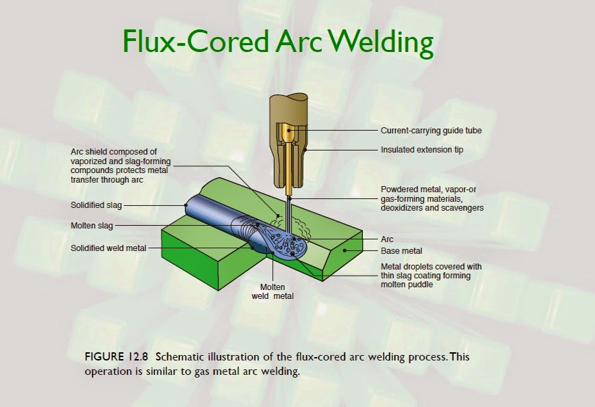
FCAW or Flux Cored Arc Welding Learn Basic Welding Techniques
Yeswelder Flux 135 Settings Chart
MIG FluxCored Welding Calculator Electrical Components
Flux Core Welding Settings Chart

How To Set Up A Flux Core Welder

What flux core wires to keep on hand? Welding Site
Flux Core Welding Chart
Flux Core Welding Chart
MIG & Flux Core Welding Wire Types & Specification (with Chart) Weld Guru
Joint Design, Fitup, Backup, Position, Bead Size And Stickout May Alter Conditions.
Web What Material Are You Welding?
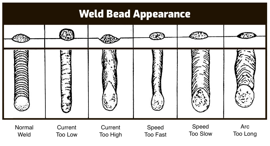
Properly Adjusting These Parameters Is Crucial For Achieving An Optimal Balance Between Penetration And Deposition Rate.
Web Flux Core Welding Settings Chart.
Related Post:
